
A tool for fast and precise conversion from EDA to FEM
Industrial applications
Key Features
- Quick and easy tool to build 3D FEM models for structural and thermal analysis.
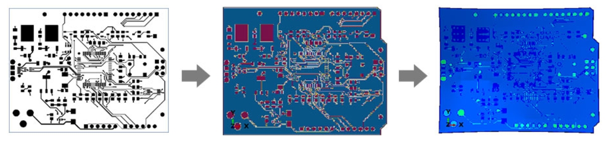
- Convert EDA files directly to 3D FEM models through image recognition.
- The effective global model with equivalent material will be calculated during the meshing process to shorten modeling time by more than 90% compared to the original one.
- With AI technology to distinguish the direction of layout and establish a more accurate equivalent model.
- In a hybrid model, we mixed the effective global model we generated by PCB Module and real model to reduce the scale of the FEM model, greatly shrink the calculation time and obtain more accurate analysis results.
- Supports a variety of FEM solvers (Abaqus, CALCULIX, ANSYS)
Pre processor
Main Window
After importing the EDA file, you can see three major blocks from the main window:
- EDA Source: EDA file source path.
- Stack Information: Stack information of all layers, including material, thickness, properties, etc.
- Mesh Setting: Mesh-related settings for finite elements, and others settings.
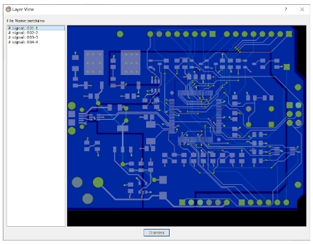
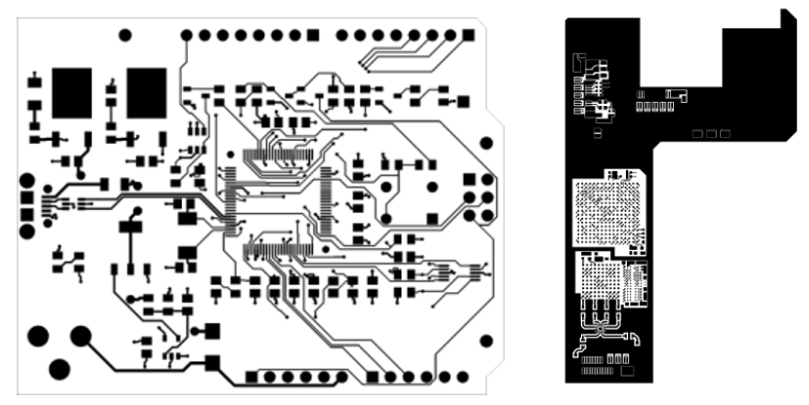
Layer View
You can view and check the 2D layout of each layer.
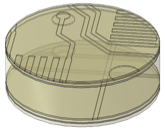
Choosing the most concerned areas and generating a hybrid model.
- Choosing the hot zone and creating the real model of the hot zone.
- Meshing the real model and using the tie constraint to link the real model and the effective global model.
- Submitting the analysis and getting more accurate results
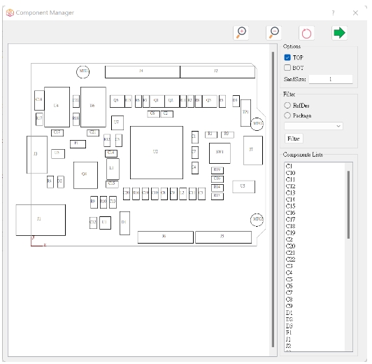
Component Manager
If the EDA file contains the definitions of electronic components, you can see the information of electronic components in the Component Manager. If you want to export components, you can set the components to be output in this window, and you can also edit each component.
Other settings
In the“Edit”tab, you can set the working path, the number of CPU cores, nonlinear material options, advanced meshing settings and so on. The FEM model generated by the preprocessor currently supports Abaqus/CAE,ANSYS and CalculiX to open and browse. Users can use CAE softwares to perform calculations after setting other required boundary conditions.
Solver
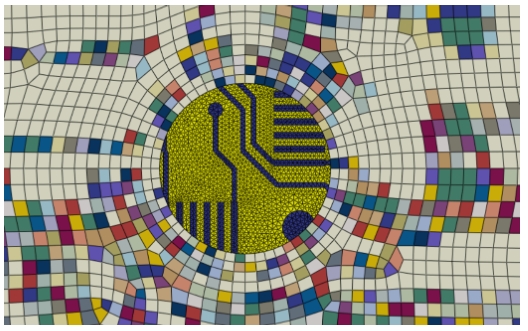
The solver of the PCB Module is based on Python, and combined with third-party software KLayout and Gmsh, through image recognition and parallel processing, it can achieve the result of quickly establishing an equivalent finite element model.
We also add an AI system to deal with the different patterns using anisotropic materials , so that users can use a small number of elements, combined with AI recognition, to obtain more accurate results than the original global equivalent model.
PCB Module Introduction
Input Data Format
- ODB++
- AutoCAD DXF
- GDSII
- Images (ex: .png)
Material Behavior
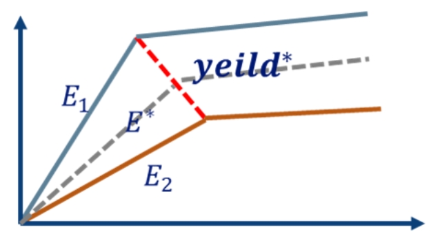
- Linear equivalent material
- Nonlinear equivalent material
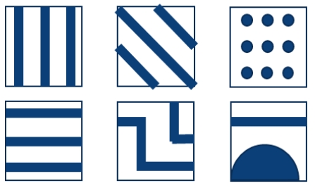
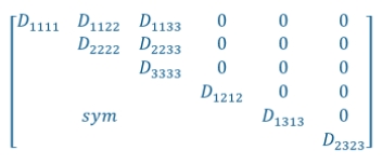
AI system with anisotropic materials
- Learning hundreds of thousands of graph distributions through AI systems
- Let the equivalent material model apply the correction of materials properties in different XY directions according to the AI system
- More precise results with fewer elements
Hybrid Model
- Choosing the hot zone and creating the real model of the hot zone.
- Meshing the real model and using the tie constraint to link the real model and the effective global model.
- Submitting the analysis and getting more accurate results
High-Performance Computing
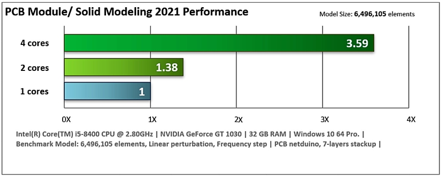
Multiple processors can be used to reduce run time during pre-processing and analysis. The number of CPUs is unlimited in PCB Module pre-processing, while CPUs used in Abaqus depend on the number of tokens purchased.